Fuel Tank
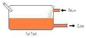
The fuel tank doesn't need much explanation other than it has the usual outlet at the base of the tank to feed the external electric pump and a return for excess fuel sent back by the main system.
Although it's name suggests that it may operate under electronic control, the K-Jetronic injection system is purely mechanical in operation. It is in fact one of the simplest mechanical fuel injection (MFi) systems around as unlike many other contemporary MFi systems it does not incorporate any mechanically driven parts. Instead, it uses mass airflow to meter a constant flow of fuel to the injectors making it a continuous injection system. There are some additional parts that are electrically operated that deal with cold starting etc.. but the primary operation of the system is purely mechanical.
The main system consists of the following:
Pressurised Fuel Supply System
Fuel Pressure Control Valve
Fuel Metering Unit
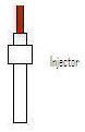
Injectors
Air Bypass
Plus the cold start and warm up system
The job of the fuel supply system is simply to provide a constant supply of fuel to the metering unit but at a stable rate. It consists of four components: Fuel Tank, Pump, Accumulator and Filter.
Fuel Tank
The fuel tank doesn't need much explanation other than it has the usual outlet at the base of the tank to feed the external electric pump and a return for excess fuel sent back by the main system.
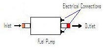
The fuel pump is an electrically driven self contained device that is mounted close to the fuel tank.Fuel pump output is approx 75psi.The pump is actuated by the fuel pump relay.
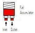
The fuel accumulator is necessary to ensure a steady stable supply of fuel to the metering unit. It is basically a small spring loaded reservoir that is half filled by the fuel pump against the pressure of the internal spring and effectively dampens out any pulsing effects from the fuel pump. It could be thought of as a kind of fuel filled balloon.
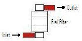
The final item is the filter and is also pretty self explanatory.
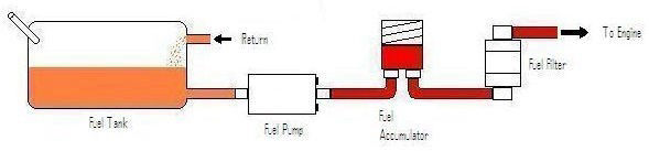
Put it all together and you get the
Pressurised Fuel Supply System.
The fuel being presented to the metering unit from the supply system needs some measure of control to keep it at the correct pressure. This is achieved with the fuel pressure control valve.The valve is built into the side of the main metering unit and comprises of a simple plunger and spring arrangement. The spring tension is pre-set with adjustment at the factory being achieved with the use of shims under the spring.
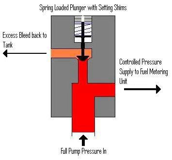
As the fuel pressure entering the metering unit overcomes the spring the plunger is pushed off it's seat opening up the return passage to the fuel tank. When fuel flow demands are low the excess pressure will hold the plunger far off its seat. As the fuel flow demand increases and the system pressure starts to drop the plunger is pushed towards its seat by the spring against the reduced fuel pressure reducing the bleed off until equilibrium is restored.. This results in maintaining the correct fuel pressure to the metering unit as less fuel is now being bled away.
This is the main component at the heart of the system and as with everything else it's operation is pretty simple. It adjusts the amount of fuel flowing to the injectors by a direct mechanical link to the amount of air flowing into the engine. It comprises of two parts, the fuel metering device and the air flow sensor. Both of these two items are completely mechanical and will be looked at in turn.
The general layout and operation of this device is best described by using diagrams. Remember that the diagrams are simplified to aid explanation but as you won't ever be taking the unit apart the minor detail changes do not mater.
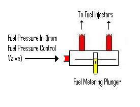
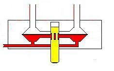
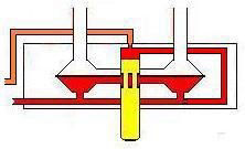
The picture shows a very basic diagram of the Fuel Metering Device located on the large Fuel Metering Unit. As can be seen, it has a fuel inlet to receive fuel at a controlled pressure from the Fuel Pressure Control Valve. It also has the supply lines leading away from it to the individual injectors. Finally it has a Fuel Metering Plunger.
This component is at the heart of the Fuel Metering Devices operation.
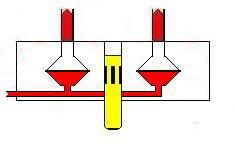
The Fuel Metering Device houses a number of chambers, one for each injector. The above picture only shows two of these chambers for clarity. The chambers are split through the middle by a metal dividing plate giving an upper and a lower section. The lower sections are fed pressurized fuel via internal passages. The upper sections are connected to the Injectors.
Now, in order for the fuel to get to the injectors, it must somehow get past the metal plate to get to the upper section of it's respective chamber. This is where the Fuel Metering Plunger comes in.
The plunger has a number of grooves in it, one for each injector, or more correctly, one for each chamber. It sits in the centre of the Fuel Metering Device in the middle of the four chambers. Each chambers upper and lower sections are connected to the plunger via passageways that line up with each of the previously mentioned grooves. It is these grooves that allow the transfer of fuel from the lower section of each individual chamber to it's corresponding upper chamber.

The further into the unit the plunger is moved the more of the groove is exposed to each chambers passage and so the rate of fuel flow is increased.
So we now know that the rate of fuel flow to each injector is controlled by the position of the central Fuel Metering Plunger. But what controls the position of the plunger? It's time to look as the Air Flow Sensor.
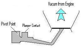
The airflow sensor mechanism consists of a lever pivoted at one end with a counter balance and attached to a large circular plate at the other. The circular plate is positioned in the shallow end a conical tube, the larger end being attached to the engines inlet manifold via the throttle butterfly. The other side of the tube below the plate is open to atmosphere via the air filter. Just next to the pivot on the lever is a contact point that acts on the plunger in the middle of Fuel Metering Device.
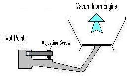
Now, in order to allow for a certain amount of adjustability, the contact point on the lever for the fuel metering plunger is adjustable as shown below. However, it is factory set on a rig and should not be played with.
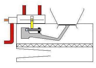
The whole assembly is mounted in the Fuel Metering Unit box as shown. The Fuel Pressure Control Valve and the Fuel Metering Device have been simplified for clarity.
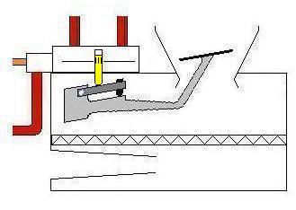
Now, this next bit is important. It is not the pressure of air rushing in pushing up on the bottom of the plate that makes the arm swing upwards on it's pivot. It is the drop in air pressure above the plate caused by the vacuum of the engine sucking in the air in the inlet system that causes it to rise. As it does rise it pushes the Fuel Metering Plunger further up into the Fuel Metering Device uncovering more area of the grooves to each of the passages to the upper sections of each chamber, thus allowing a higher rate of fuel flow to the corresponding injectors.
Now you might be thinking "Why doesn't the plate just go all the way up each time?" There are two reasons for this, firstly the fact that the metering plates is in a conical tube means that the further up it rises the larger an area of bypass around the edge of the plate is opened up. Secondly, the Fuel Metering Plunger itself has an opposing force applied to its top end supplied by fuel pressure. A tapping from the internal fuel passageways in the Fuel Metering Device supplies fuel pressure to the top side of the plunger. Of course if it was just subjected to full fuel pressure then the airflow sensor mechanism would never over come it. Therefore the fuel pressure is bled away through a restricted orifice back to the return line.
So we have the force of the airflow sensing mechanism trying to push the plunger up to increase the rate of fuel flow and a restricted fuel pressure bleed acting on top of the plunger trying to resist upwards movement. This results in the plunger finding it's point of equilibrium where the opposing forces match. But what changes the amount of influence that the airflow sensing mechanism has on the position of the plunger? Well, quite simply as its name suggests it's the amount or rate of airflow through the conical tube. But what effects this rate of airflow through the tube? Well, one is the RPM of the engine. More RPM results in a higher rate of airflow to meet the demands of the engine as it draws in more air. There is of course something else involved though, something that gives us control over the engine. The Throttle Body.
The throttle body is basically like a tap that controls the amount of air available to the engine. It is mounted directly onto the end of the plenum chamber on the inlet manifold and contains a simple but accurately fitting butterfly valve.
In order to provide a degree of adjustability for the idle speed a small air bypass is incorporated into the throttle body with an adjustable restrictor. This allows just enough air to pass round the closed throttle butterfly valve to maintain idle running speed of the engine.
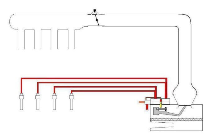
The open end of the throttle body is connected via a large flexible rubber pipe to the large open top of the conical tube on the Fuel Metering Unit. Thus the whole basic package resembles that shown.
You can see we have now also added the Fuel Injectors to there respective fuel lines. The injectors are purely mechanical and very simple. They are not pulsed open and closed like electronic injectors in modern EFi systems, as already stated this is a purely mechanical system. Instead they simply open as soon as a high enough fuel pressure is applied to them to overcome the internal spring loaded valve. This ensures that a high enough pressure is present to achieve the correct spray pattern through the injectors nozzle and also prevents fuel from dribbling out of the injectors when the engine is switched off. There is of course no sequencing system on this injection system so once the engine is running fuel is constantly being sprayed from all four injectors regardless of what stage of the four stroke cycle each particular cylinder is at. The amount of fuel being sprayed is of course metered so that when the inlet valve does finally open the amount of fuel sitting behind the valve in the inlet tract is correct for that charge.
So now by adding the supply system we nearly have the full basic set-up.
There's just one more thing to add, the Air Bypass Valve.
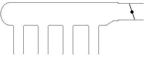
The overrun shut-off valve is an add on to get around an inherent problem with the basic system.When the throttle butterfly is suddenly closed (by you taking your foot off the accelerator when changing gear etc...) the airflow sensor plate tends to hang in the air whilst the air in the inlet system continuous to pass by to fill the depression or vacuum in the inlet trunking between the airflow meters plate and the now closed throttle butterfly. This of course holds the Fuel Metering Plunger in the raised position resulting in over fueling and possibly stalling of the engine.

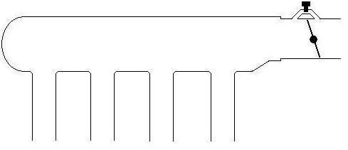
To get around this problem, an air bypass valve called the Overrun Shut-off Valve is fitted. This is plumbed in between the bottom side of the airflow metering plate and the trunking at the top side of the metering plate. It opens whenever the throttle is closed to allow direct access for air trapped below the airflow metering plate to get past and fill the void in the inlet trunking.
This valve is a simple solenoid valve that is either open or closed with no in between settings. It is normally in the closed position sealing off the bypass but is activated open by a small switch on the throttle body that makes contact whenever the throttle is fully closed.This may seem at odds with the components name 'Overrun Shut-off Valve' but it effectively shuts off the fuel supply by causing the airflow sensor plates to drop back to its idle position.
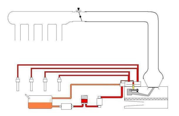
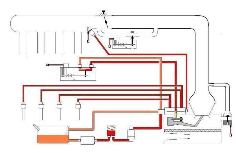
To put it all into context, here it is fitted.
So there you have the basic system. Fuel from the Fuel Tank is pressurized by the Fuel Pump, passes through the Fuel Accumulator which smooths out any pulsing effects from the pump that would upset the operation of the metering unit, and from there is routed through the Fuel Filter and on to the Fuel Pressure Control Valve. This supplies a set pressure supply to the Fuel Metering Device, the excess being routed back to the fuel tank.The Fuel Metering Device distributes fuel equally to each of the constant flow injectors at a metered rate determined by the position of the Fuel Metering Plunger. The position of the Fuel Metering Plunger is controlled by the position of the Air Flow Sensor that reacts to the differing pressures and rates of airflow in a conical section of the inlet tract. Airflow through the inlet tract is controlled by the Throttle Body and an Overrun Shut-off Valve is fitted to induce the rapid resetting of the Airflow Sensor Mechanism to it's idle position whenever the throttle is fully closed.
There is of course a bit more to it than that though, this basic system may be fine for normal running but there's the cold start and warm up system to add to it yet.
As most older readers will know (showing my age now as well), engines equipped with a Carburetor (google it!) came with a device to assist with cold starting known as the 'choke'. The choke was a simple affair that did two things. First it opened the main throttle butterfly via a cam arrangement to increase the airflow and so power setting into the engine. Secondly, it simultaneously closed a second butterfly valve upstream of the main throttle butterfly causing a restriction to the incoming airflow. Without getting too technical, what this did was increase the amount of 'vacuum' being felt on the jets in the carburetor drawing more fuel out than would normally be drawn. This resulted in a richer mixture.
So the results of its actions were to increase the amount of basic air/fuel mixture entering the engine by slightly opening the throttle and to then richen the mixture by increasing the amount of fuel entering compared to the amount of air.
The Cold Start System does pretty much the same thing, it just does it in a different manner. We'll start with increasing the amount of basic air/fuel mixture entering the engine. This is achieved with the help of the Auxiliary-Air Device.
Auxiliary-Air Device
This is basically another air bypass valve mounted alongside the throttle body, only this one is progressive in operation and temperature controlled. At first glance you could think it could be compared to a modern Idle Speed Control Valve but its operation is very different.
I'll start off with explaining what it does first as it's very simple. By providing a bypass route around the closed throttle butterfly it allows more air to enter the engine. This is just like the cam on the old choke mechanism cracking open the butterfly valve in the old carburetor. This increase in air flowing into the engine is of course felt by our old friend the Airflow Sensing Mechanism in the Fuel Metering Unit. This starts to lift, pushing up the Fuel Metering Plunger and proportionally increasing the fuel flow to the injectors. So there we have the first part completed, the increase of the basic air/fuel mixture entering the engine. Here's how it works:
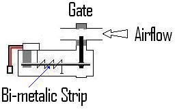
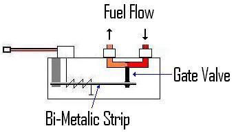
The valve consists of a sliding gate valve controlled by a bi-metalic strip. Now, for those who didn't pay enough attention in science class, a bi-metalic strip is quite literally two strips of metal stuck back to back. The two strips are of different types of metal with noticeably different rates of heat expansion. This means that as the bi-metalic strip heats up, the differing expansion rates of the two metals cause the strip to bend as one expands more than the other. These strips are commonly found in kettles where the heat of the steam from the boiling kettle causes a bi-metalic strip to bend and switch off the power.
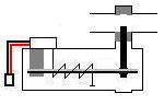
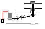
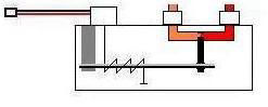
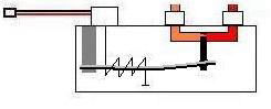
Now, in the Auxiliary-Air Device, the free end of the bi-metalic strip is attached to the gate valve. In its cold state with the strip straight, the gate valve is held fully open giving full extra airflow through the bypass. But as the strip starts to warm up and so starts to bend, it moves the gate valve towards the closed position. By the time the strip has reached normal running temperature the gate valve is fully closed blocking all airflow through the bypass.
So what causes the bi-metalic strip to get hot? The strip is heated by an electric heating element inside the unit. This element is activated on engine start and so starts to heat the bi-metalic strip straight away. It does however take time for the strip to expand and close off the gate valve. The Auxiliary-Air Device is also carefully positioned so as to be exposed to the general heat soak of the engine which will also cause expansion of the bi-metalic strip. This means that if the engine is already warm on starting then the Auxiliary-Air Device already be closed.
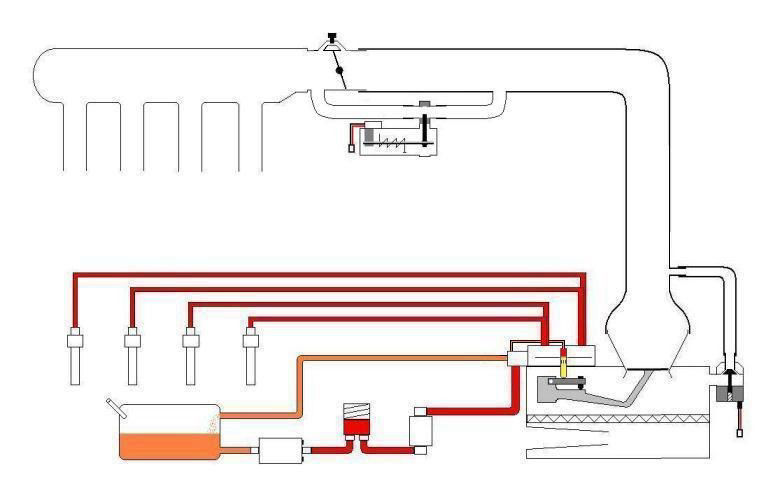
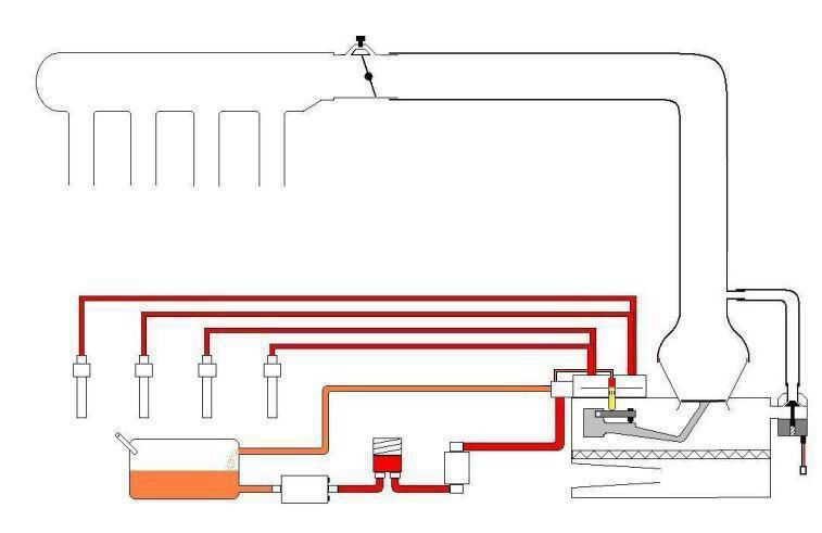
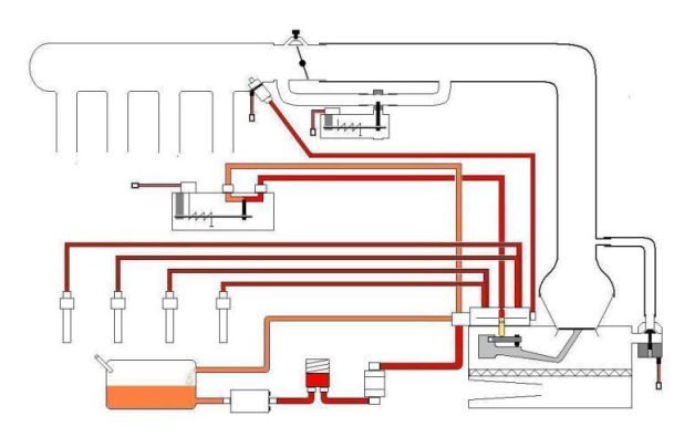
Here it is added to the system.
Now we need to richen the mixture. But if the fueling is being controlled by the position of the Fuel Metering Plunger within the Fuel Metering Device, and that itself is controlled by the Airflow Sensor Mechanism, how can we richen the mixture without further increasing airflow? Well, there are two ways actually.
Warm-Up Regulator
Going back to that Fuel Metering Plunger within the Fuel Metering Device, if you remember it is pushed up by the Airflow Sensing Mechanism to increase fuel flow with increasing airflow. Now, opposing this force and maintaining some form of control over the Airflow Sensing Mechanisms influence on the plunger was a fuel pressure tapping that returned to the fuel tank through a restictor. How about if we reduced the pressure of the fuel above the plunger to allow the Airflow Sensing Mechanism to push it up further for any given rate of airflow? It wouldn't be hard to do, you'd just have to have less of a restriction in the return line to the tank to allow the pressure to leave quicker. I think it's time to take a look at the Warm-Up Regulator.
Now the observant amongst you might notice a few similarities between this and the Auxiliary-Air Device. That's because it is extremely similar to the Auxiliary-Air Device. The only difference between the two is that this device slowly closes off a fuel bypass as opposed to an air bypass. Well that's not quite right, it never closes off fully, it just reduces flow to a predetermined minimum setting.
Just like the Auxiliary air device it has a bi-metalic strip to do the work which is electrically heated on starting the engine.
It is also strategically located on the engine so as to be exposed to the effects of heat soak from the engine which also causes the bi-metalic strip to bend as the engine warms up.
So that's how it works, but how does it fit in with the Fuel Metering Device? Simple, it replaces the restrictor in the return line to the tank from the top of the Fuel Metering plunger thus:
Wow, we're almost there. Just one more bit to add now. You see, even though the Warm-Up Regulator performed fine whilst the engine was warming up, the engine still needed a fuel boost for initial starting when cold that the Fuel Metering Device just could not provide in anything like a controlled manner. In the old days of carburettors that were common place when this system was developed you could give the accelerator pedal a couple of pumps and the accelerator pump within the carburettor would have supplied that extra boost. But there is no accelerator pump on an injected engine, all you are doing is opening the throttle butterfly. Therefore there was only one thing to do, add an extra fuel supply!
Cold Start Valve
The Cold Start Valve is merely an extra fuel injector and is rather rudimentary by todays standards. It is mounted just behind the Throttle Body in the entrance to the Plenum Chamber and pre-primes the air entering the cylinders with a mist of fuel. Unlike the main injectors this one is electronically triggered. It still isn't pulsed like modern injectors, instead it provides a steady flow until the electrical supply is removed. It receives its supply of fuel from a tapping from the main Fuel Metering Unit.

The valve is electrically activated as soon as the starter motor is energized to start the fuel flowing and from then on is controlled by a thermo switch in the engine block so that when the engine passes through a pre-determined temperature as it warms up the injector is de-energised. This thermo switch is nothing more than yet another bi-metallic strip only this time it is merely breaking a circuit just like the one that switches off your kettle once the water has boiled.
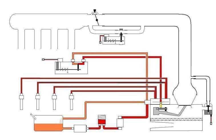
So lets add it to the big picture and see the final piece of the jigsaw puzzle slot into place!
So there we have it, the basics of the wonderful Bosch K-Jetronic mechanical fuel injection system. The components themselves do of course differ slightly from the pictures I have drawn but the basic principals are the same.
I hope you find this useful and that you feel more confident about the workings of your K-Jet system because of it.


Made with
HTML Website Creator